Safety precautions
WARNING
To prevent injury or fire, take the following
precautions:
• Mounting and wiring this product requires skills and
experience. For safety’s sake, leave the mounting and
wiring work to professionals.
• To prevent a short circuit, never put or leave any metallic
objects (such as coins or metal tools) inside the unit.
• If the unit starts to emit smoke or strange smells, turn
off the power immediately and consult your Kenwood
dealer.
• Do not touch the unit during use because the surface of
the unit becomes hot and may cause burns if touched.
CAUTION
To prevent damage to the machine, take the following
precautions:
• Be sure the unit is connected to a 12V DC power supply
with a negative ground connection.
• Do not open the top or bottom covers of the unit.
• Do not install the unit in a spot exposed to direct
sunlight or excessive heat or humidity. Also avoid places
with too much dust or the possibility of water splashing.
• When replacing a fuse, only use a new one with the
prescribed rating. Using a fuse with the wrong rating
may cause your unit to malfunction.
• To prevent a short circuit when replacing a fuse, first
disconnect the wiring harness.
NOTE
• If you experience problems during installation, consult
your Kenwood dealer.
• If the unit does not seem to be working right, consult
your Kenwood dealer.
Cleaning the unit
If the front panel gets dirty, turn off the power and wipe
the panel with a dry silicon cloth or soft cloth.
CAUTION
Do not wipe the panel with a hard cloth or a cloth
dampened by volatile solvents such as paint thinner and
alcohol. They can scratch the surface of the panel and/or
cause the indicator letters to peel off.
To prevent battery rise
When the unit is used in the ACC ON position without
turning the engine ON, it depletes the battery. Use it after
starting the engine.
Protection function
The protection function is activated in the following
situations:
This unit is equipped with a protection function for
protecting this unit and your speakers from various
accidents or problems that can occur.
When the protection function is triggered, the amplifier
stops operating.
• When a speaker wire may be short-circuited.
• When a speaker output contacts ground.
• When the unit malfunctions and a DC signal is sent to
the speaker output.
• When the internal temperature is high and unit won’t
operate.
• When detects a low impedance at the speaker
connections.
7 Wiring
• If a buzzing noise is heard from the speakers when the
engine is running, connect a line noise filter (optional) to
each of the battery wire.
• Do not allow the wire to directly contact the edge of the
iron plate by using Grommets.
• Connect the ground wire to a metal part of the car
chassis that acts as an electrical ground passing
electricity to the battery‘s negative · terminal. Do not
turn the power on if the ground wire is not connected.
• Be sure to install a protective fuse in the power cord
near the battery. The protective fuse should be the same
capacity as the unit’s fuse capacity or somewhat larger.
• When more than one power amplifier are going to be
used, use a power supply wiring wire and protective
fuse of greater current-handling capacity than the total
maximum current drawn by each amplifier.
7 Speaker selection
• Using speakers with smaller input ratings than the
amplifier’s output power would result in smoke
generation or equipment failure.
• The impedance of the speakers that are going to
be connected should be 2Ω or greater (for stereo
connections), or 4Ω or greater (for bridged connections).
When more than one set of speakers are going to
be used, calculate the combined impedance of the
speakers and then connect suitable speakers to the
amplifier.
<Example>
Take the time to read through this instruction manual.
Familiarity with installation and operation procedures will help you obtain the best performance from your new power
amplifier.
For your records
Record the serial number, found on the back of the unit, in the spaces designated on the warranty card, and in the space provided
below. Refer to the model and serial numbers whenever you call upon your Kenwood dealer for information or service on the product.
Model
KAC-M1824BT Serial number
KAC-M1824BT
Troubleshooting Guide
Symptom Remedy
Sound cannot be heard. • Check the cords and connections.
• Protection circuit may be activated. Check connections. (
\
<Protection function>)
• Blown fuse. Replace the fuse.
• The speaker cord is shorted. After check the speaker cord and fixing the cause of the short, replace the fuse.
The sound quality is bad.
(The sound is distorted.)
• Connect the speaker cord properly checking the ª/· of the terminals and wires well.
• Connect the speaker cord again so that it is not pinched by anything.
No bluetooth device is detected. • Reset the unit. (
\
<How to reset>)
Bluetooth pairing cannot be made. • Delete pairing information from both the unit (
\
<How to reset>) and the Bluetooth device, then perform
pairing again.
Sound is being interrupted or skipped
during playback of a bluetooth audio
player.
• Reduce the distance between the remote control unit and the Bluetooth audio player.
• Other Bluetooth devices might be trying to connect to the unit.
The connected Bluetooth audio player
cannot be controlled.
• Check whether the connected Bluetooth audio player supports Audio/Video Remote Control Profile (AVRCP).
(Refer to the instructions of your audio player.)
• Disconnect and connect the Bluetooth player again.
FCC WARNING
This equipment may generate or use radio frequency energy. Changes or modifications to this
equipment may cause harmful interference unless the modifications are expressly approved in the
instruction manual. The user could lose the authority to operate this equipment if an unauthorized
change or modification is made.
FCC NOTE
This equipment has been tested and found to comply with the limits for a Class B digital device, pur-
suant to Part 15 of the FCC Rules. These limits are designed to provide reasonable protection against
harmful interference in a residential installation. This equipment may cause harmful interference to
radio communications, if it is not installed and used in accordance with the instructions. However,
there is no guarantee that interference will not occur in a particular installation. If this equipment
does cause harmful interference to radio or television reception, which can be determined by turn-
ing the equipment off and on, the user is encouraged to try to correct the interference by one or
more of the following measures:
• Reorient or relocate the receiving antenna.
• Increase the separation between the equipment and receiver.
• Connect the equipment into an outlet on a circuit different from that to which the receiver is con-
nected.
• Consult the dealer or an experienced radio/TV technician for help.
CAUTION
This equipment complies with FCC/IC radiation exposure limits set forth for an uncontrolled environment and
meets the FCC radio frequency (RF) Exposure Guidelines in Supplement C to OET65 and RSS-102 of the IC radio
frequency (RF) Exposure rules. This equipment has very low levels of RF energy that it deemed to comply with-
out maximum permissive exposure evaluation (MPE). But it is desirable that it should be installed and operated
keeping the radiator at least 20cm or more away from person’s body (excluding extremities: hands, wrists, feet
and ankles).
Under Industry Canada regulations, this radio transmitter may only operate using an antenna of a type and
maximum (or lesser) gain approved for the transmitter by Industry Canada. To reduce potential radio interfer-
ence to other users, the antenna type and its gain should be so chosen that the equivalent isotropically radi-
ated power (e.i.r.p.) is not more than that necessary for successful communication.
IC (Industry Canada) Notice
This device complies with Industry Canada licence-exempt RSS standard(s). Operation is subject to the following
two conditions:
(1) This device may not cause interference, and
(2) this device must accept any interference, including interference that may cause undesired operation of the
device.
The term “IC: ” before the certification/ registration number only signifies that the Industry
Canada technical specification were met.
Contains Bluetooth Module FCC ID: YZP-RBFAC21SA
Contains Bluetooth Module IC: 7414A-RBFAC21SA
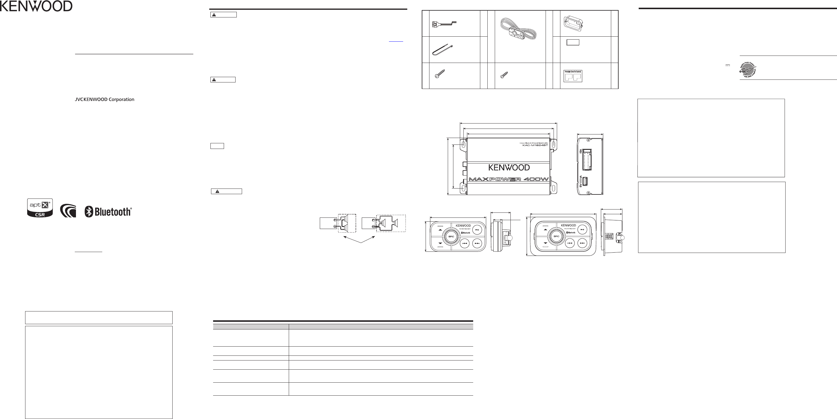
Specifications
Specifications subject to change without notice.
Audio
Max power output ...............................................................................400 W
Rated power output (+B = 14.4V)
Stereo (4 Ω)....................................45 W × 4 (1 kHz, ≤ 1.0 % THD)
Bridged (4 Ω) ................................90 W × 2 (1 kHz, ≤ 1.0 % THD)
Speaker impedance ...............................4 Ω (2 Ω to 8 Ω allowable)
(Bridged connection: 4 Ω to 8 Ω allowable)
Frequency response (+0, –1 dB)............................ 20 Hz – 20 kHz
Signal to noise ratio..............................................................................90 dB
Input impedance ...................................................................................10 kΩ
USB Charge
Maximum supply current ...............................................DC 5 V
1 A
Bluetooth
Version ................................................................. Bluetooth Ver.3.0 + EDR
Supported codecs ........................................................... SBC/AAC/aptX
Profile ...................A2DP (Advanced Audio Distribution Profile)
AVRCP (Audio/Video Remote Control Profile)
General
Operating voltage ................................ 14.4 V (11 – 16 V allowable)
Current consumption ............................................................................15 A
Dimensions (W × H × D) ......................................145 × 45 × 99 mm
5-11/16 × 1-3/4 × 3-7/8 inch
Weight .......................................................................................1.4 kg (3.1 lbs)
CEA-2006
RMS Watts per channel @ 4 ohms, ≤ 1% THD+N
.....................................................................................45 W × 4
Signal to noise ratio
(Reference: 1Watt into 4 ohms) ......................74 dBA
157 mm (6-3/16”)
169 mm (5-5/8”)
45 mm (1-3/4”)145 mm (5-11/16”)
99 mm (3-7/8”)
76 mm (3”)
7 Dimensions
7
Accessories
1
DC cable
1
4
Remote control unit
1
6
Mounting
bracket
1
2
Wire band
2
7
Double-side adhesive tape
1
3
ø 4 x 16 mm
4
5
ø 3 x 8 mm
1
8
Protective
cover
1
Self-tapping Self-tapping
99.0 mm (3-7/8”)
31.3 mm (1-1/4”)
27.8 mm
(1-1/16”)
58.1 mm (2-5/16”)
84.0 mm (3-5/16”)
29.3 mm (1-3/16”)
16.8 mm (5/8”)
45.1 mm (1-3/4”)
Combined impedance
2Ω
8Ω
4Ω
4Ω 4Ω
4Ω
COMPACT BLUETOOTH® 4 CHANNEL DIGITAL AMPLIFIER
INSTRUCTION MANUAL
A-2 B-2
Ground wire (Black)
L
L
R
L
R
R
L
L
R
R
LINE OUTLINE INOUTPUT MODE
REMOTE
FADER
STEREO 4ch
FRONT REAR
BRIDGED 2ch
OUTPUT MODE
STEREO 4ch BRIDGED 2ch
OUTPUT MODE
STEREO 4ch BRIDGED 2ch
R
L
FRONT
L
FRONT
R
REAR
L
REAR
R
A.ch
B.ch
Type A: RCA INPUT connection
Type B: SPEAKER INPUT connection
White
White/Black
Gray
Gray/Black
Green
Green/Black
Purple
Purple/Black
Power control wire (Blue)
AFTER MARKET HEAD UNIT only
Car fuse box
Battery
FACTORY INSTALLED
HEAD UNIT
SPEAKER OUTPUT
FRONTREAR
AFTER MARKET
HEAD UNIT
REAR
FRONT
RL
A-1 B-1
Battery wire (Yellow)
BATT
ACC
CAUTION
• Do not install in the below locations;
(Unstable location, In a location that interferes with
driving, In a location that gets wet, In a dusty location, In
a place that gets hot, In a place that gets direct sunlight,
In a location that gets hit by hot air)
• Do not install the unit under the carpet. Otherwise heat
build-up occurs and the unit may be damaged.
• Install this unit in a location which allows heat to easily
dissipate. Once installed, do not place any object on top
of the unit.
• The surface temperature of the amplifier will become
hot during use. Install the amplifier in a place where
people and other substances that are sensitive to heat
will not come into contact with it.
• When making a hole under a seat, inside the trunk,
or somewhere else in the vehicle, check that there
is nothing hazardous on the opposite side such as a
gasoline tank, brake pipe, or wiring harness, and be
careful not to cause scratches or other damage.
• Do not install the unit on rear tray or near the air bag
safety parts.
• The installation to the vehicle should securely fasten the
unit to a place in which it will not obstruct driving. If the
unit comes off due to a shock and hits a person or safety
part, it may cause injury or an accident.
• After installing the unit, check to make sure that
electrical equipment such as the brake lamps, turn
signal lamps and windshield wipers operate normally.
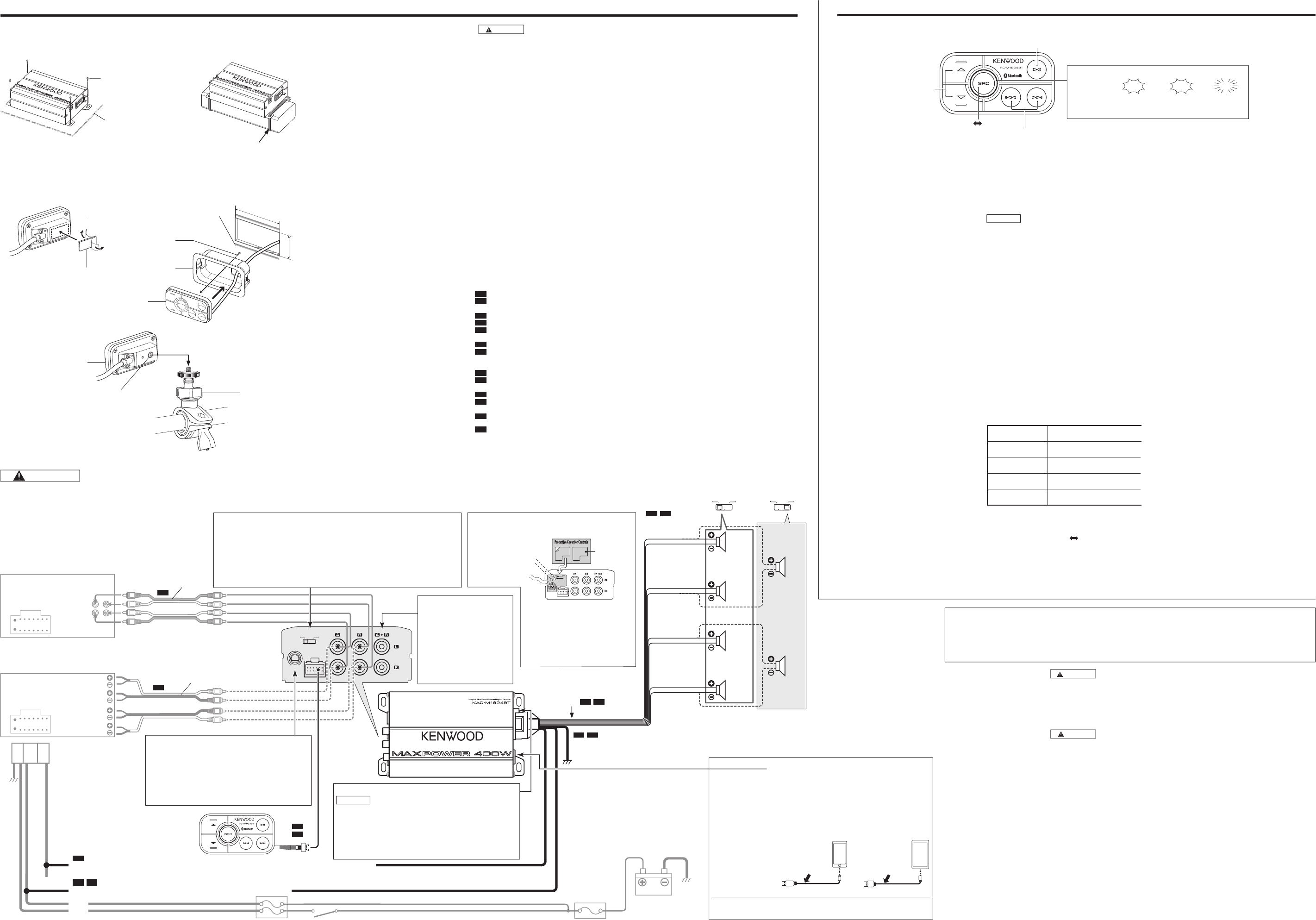
7 Installation procedure
Read the instruction manual well to select the proper
connection and setting.
1. Remove the ignition key and disconnect the
negative · terminal of the battery to prevent
short circuits.
2. There are two options:
* Refer to “Connection” as below.
Type A: RCA INPUT connection
A-1 Connect the battery wire.
A-2 Connect the ground wire to chassis ground of
v
ehicle.
A-3 Connect the power control wire.
A-4 Connect the speakers.
A-5 Connect the DC cable into the connector at KAC-
M1824BT.
A-6 Connect the RCA cable.
A-7 Connect the remote control unit.
Type B: SPEAKER INPUT connection
B-1 Connect the battery wire.
B-2 Connect the ground wire to chassis ground of
vehicle.
B-3 Connect the speakers.
B-4 Connect the DC cable into the connector at KAC-
M1824BT.
B-5 Connect the wire from the FACTORY INSTALLED
HEAD UNIT.
B-6 Connect the remote control unit.
3. Attach the unit.
4. Connect the negative · terminal of the battery.
Supported Bluetooth profiles
– Advanced Audio Distribution Profile (A2DP)
– Audio/Video Remote Control Profile (AVRCP)
Supported Bluetooth codecs
– Advanced Audio Coding (AAC)
– aptX Codec (aptX)
NOTE
• Depending on the Bluetooth version of the device, some
Bluetooth devices may not be able to connect to this unit.
• This unit may not work with some Bluetooth devices.
• Signal conditions vary, depending on the surroundings.
7 Pair a Bluetooth device
When connecting a Bluetooth device to the unit for the first
time, perform pairing between the unit and the device. Refer
also to the manual supplied with your Bluetooth device.
1. Press SRC to enter Bluetooth mode.
• Illumination blinks in blue slowly and start paring.
• [RC-M1824BT] will appear on the Bluetooth device.
2. Press and hold
£
8
• Illumination will light up in blue when the Bluetooth
connection is established.
• To cancel the paired device and enter searching mode
again, press and hold £8.
• Up to three devices can be registered (paired) in total.
• Once the paring is completed, the Bluetooth device will
remain registered in the unit. Next time you connect the
Bluetooth device, pairing request is automatically activated.
(illumination blinks rapidly
\
lights up)
7 Start listening
1. Confirm the unit in Bluetooth mode. (Illumination
lights up in blue.)
2. Operate the Bluetooth audio player to start playback.
To
On the remote control
(Bluetooth mode only)
Playback / Pause Press
£
8
Backward skip /
Forward skip
Press 4 / ¢
Fast-backward /
Fast-forward
Press and hold 4 / ¢
Adjust the volume Press
%
or
fi
7 To adjust the brightness of the illumination
Press and hold SRC to change the setting.
Dims the button illumination. Cancels.
WARNING Remove the ignition key and disconnect the negative · terminal of the battery to prevent short circuits.
WARNING
Particular attention must be given to
making good electrical contact at the
amplifier-output and speaker terminals.
Poor or loose connections can cause
sparking or burning at the terminals
because of the very high power that the
amplifier can deliver.
CAUTION
• If sound is not output normally, immediately
turn power off and check connections.
• Be sure to turn the power off before
changing the setting of any switch.
• If the fuse blows, check wires for shorts, then
replace the fuse with one of the same rating.
• Check that no unconnected wires or
connectors are touching the car body. Do
not remove caps from unconnected wires or
connectors to prevent short circuits.
• Connect the speaker wires to appropriate
speaker connectors separately. Sharing the
negative wire of the speaker or grounding
speaker wires to the metal body of the car
can cause this unit to fail.
• After installation, check that the brake lamps,
turn signal lamps and windshield wipers
work properly.
Installation, Connection and Setting
Bluetooth function
Installation board, etc.
(thickness : 15 mm or more)
Camera screw thread
(1/4-20 UNC standard)
Speaker line to male RCA adapter
RCA cable
Bar mount kit
(Commercially available)
3
1
4
2
Adjust the volume
Playback / Pause
Illumination
Backward skip / Forward skip, Fast-backward / Fast-forward
Example A: using the screws
Example B: Flush Mount
Example C: Handle Mount
Example B: using the wire bands
Example A: Surface Mount
Fuse (15 A)
NOTE
If you can’t find the specified
capacity fuse at your store etc.,
consult your Kenwood dealer.
*
1
*
1
*
1
The output from the FACTORY INSTALLED
HEAD UNIT up to 50W can be input. The power
is turned on and off as the unit detects input
signal (SIGNAL SENSING TURN-ON). Therefore it
is not necessary to connect the power control
wire.
A-6
B-5
A-3
A-5
A-7
B-4
B-6
A-4 B-3
7 Installing the unit
7 Connection
7 Installing the remote control unit
RCA IN/SPEAKER IN Bluetooth
Select a source
Blue Blue
Red
RCA INPUT
SPEAKER INPUT
Bluetooth Pairing...
USB terminal for charging; you cannot play audio files stored on a USB device.
iPod/iPhone
KCA-iP102 / KCA-iP103 (optional accessory) or
accessory cable of the iPod/iPhone
KCA-iP102 : 30-pin type
KCA-iP103 : Lightning type
Android
Micro USB 2.0 cable
(commercially
available)
Do not leave the cable inside the car when not using.
7
4
LINE OUT terminal
The signal that’s input from
the LINE IN/REMOTE terminal is
output.
OUTPUT MODE switch
Selects the speaker output mode. Set to “BRIDGED 2ch“ for bridged connections. When output
mode is “BRIDGED 2ch“, set the FADER control to the center position.
FADER control
(Bluetooth mode only)
Adjusts the rear and front speaker output balance.
50 mm
(1-15/16”)
88 mm
(3-7/16”)
Glue
Colle
Pegamento
4
6
5
4
• iPhone and iPod are trademarks of Apple Inc., registered in the U.S. and other countries.
• Lightning is a trademark of Apple Inc.
• The “AAC” logo is a trademark of Dolby Laboratories.
• Android is trademark of Google Inc.
• The Bluetooth
®
word mark and logos are registered trademarks owned by Bluetooth SIG, Inc. and any use of such marks by JVC KENWOOD Corporation is
under license. Other trademarks and trade names are those of their respective owners.
• © 2013 CSR plc and its group companies. The aptX
®
mark and the aptX logo are trade marks of CSR plc or one of its group companies and may be registered in
one or more jurisdictions.
Protective Cover 8
LINE OUTLINE INOUTPUT MODE
REMOTE
FADER
STEREO 4ch
FRONT REAR
BRIDGED 2ch
MOISTURE
DUST
Spare
After setting up the unit, put the
protective cover 8 on the control panel.
